 CSS Drop Down Menu by PureCSSMenu.com
I designed Saguaro laminated necks with the following features:
Most anchors are composed of a steel rod or small bar that has a threaded hole the trussrod threads into. The threads are then peened to secure the rod from spinning in the anchor. I don't think most people put alot of thought into trussrod anchors. I never did until an anchor came loose inside an old strat neck I had. Most anchors concentrate the stress of the tension in the rod into a very small area, and while I've never heard of neck wood splitting because of the trussrod anchor, I believe spreading this stress over a larger area is better. The design I came up with is a 5/8" aluminum rod drilled, and milled for a bent section of a 3/16" truss rod to fit into. The bent section cannot come loose and the 5/8" rod would dissipate the rod tension over a larger surface area. 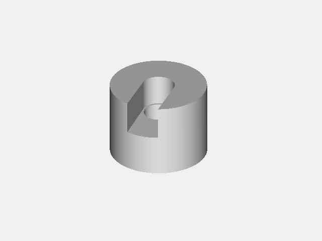
The anchor is made from 5/8" diameter aluminum rod cut into 0.475" lengths. 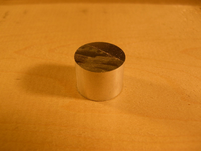
I put five of them into a jig and drill pilot holes in the center of the anchors with the CNC. 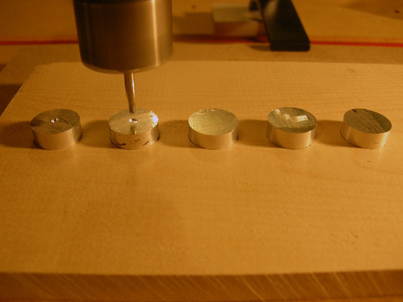
The holes are then drilled through on a drill press and tapped with a 6/32 tap so I can use 6/32 screws to hold the anchors to the jig. I then mount them in the jig and route the area for the bend in the trussrod. 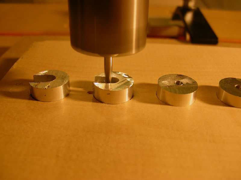
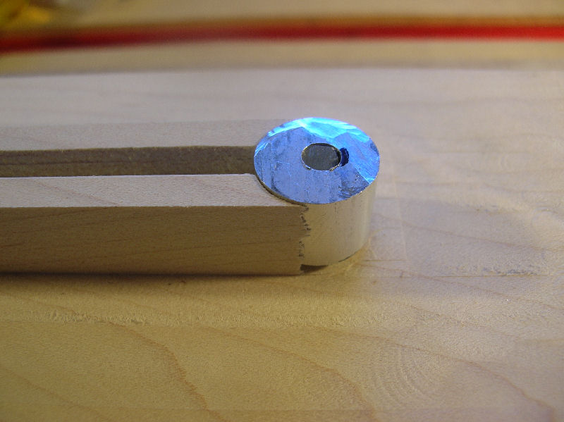
Here is a finished one with a trussrod installed. 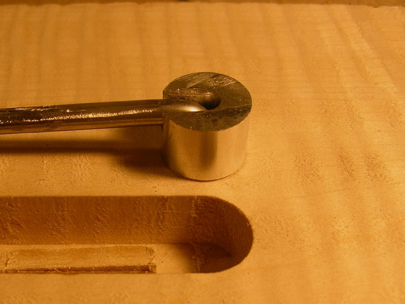
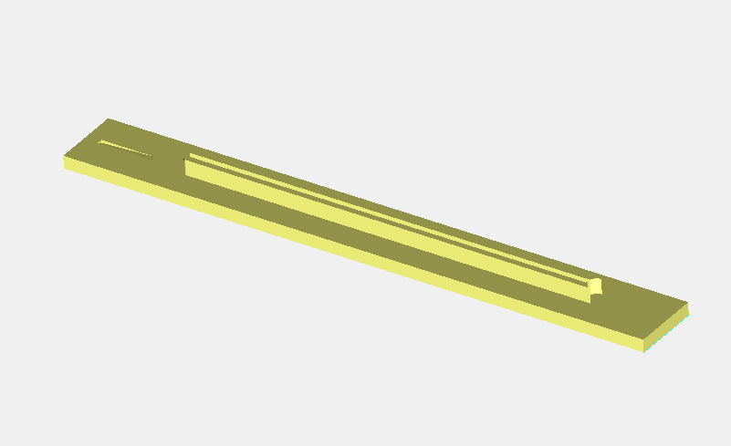
The neck base is constructed of 4/4 flamed maple with the trussrod route on top. A "cap route" is added in addition to the trussrod route. 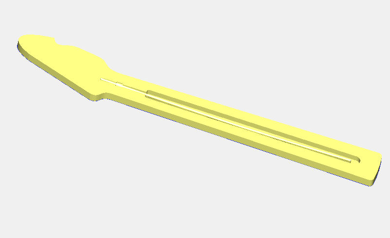
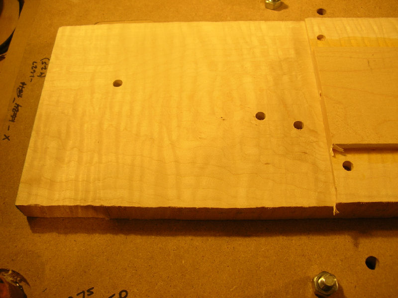
The neck base blank is mounted on the CNC with the bottom side up and the pilot holes for the tuner screws are drilled. 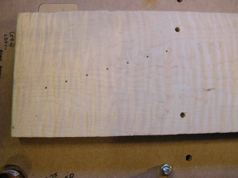
Next the holes for the stainless, threaded inserts for the neck mounting screws are drilled. 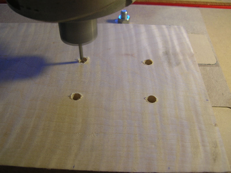
For now, that's it for the back of the neck base. 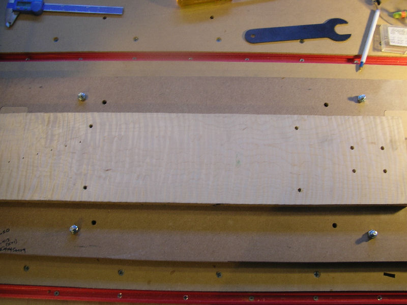
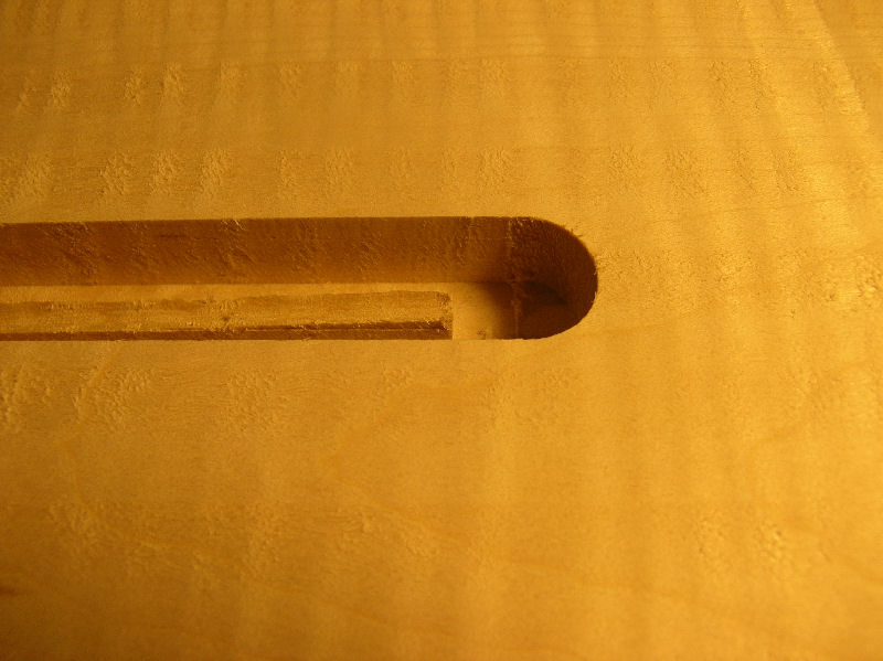
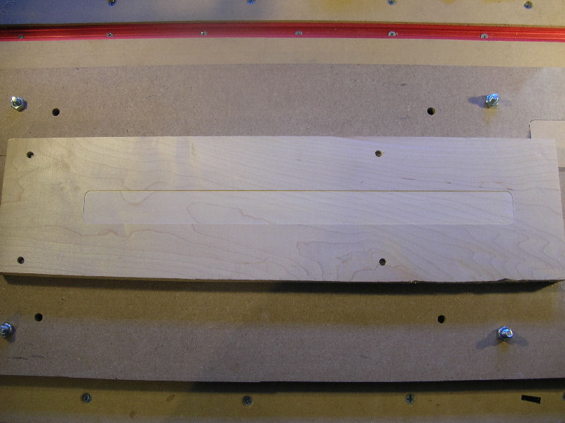
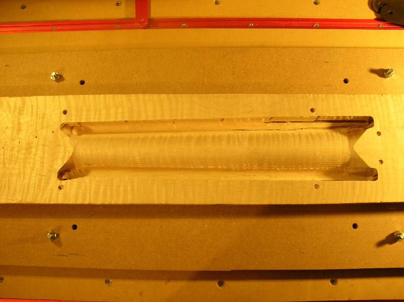
The neck base is flipped over and the trussrod channel and bullet route are routed. It is first rough cut with a 0.125 end mill and then rounded with a 0.125 ball mill so the bottom of the trussrod channel fits flush around the trussrod, unlike a flat bottomed channel. 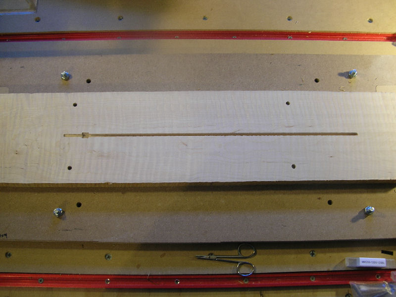
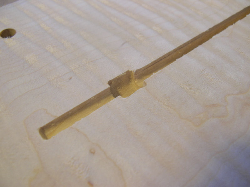
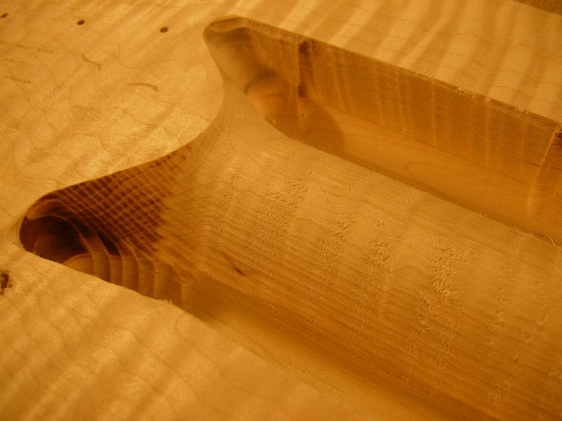
Then the anchor route. 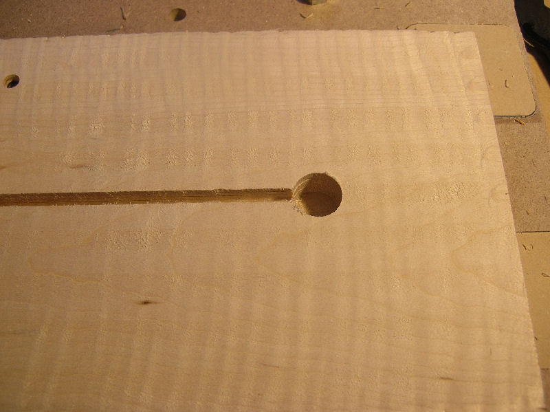
An area around the trussrod channel is then routed for the cap to fit into. 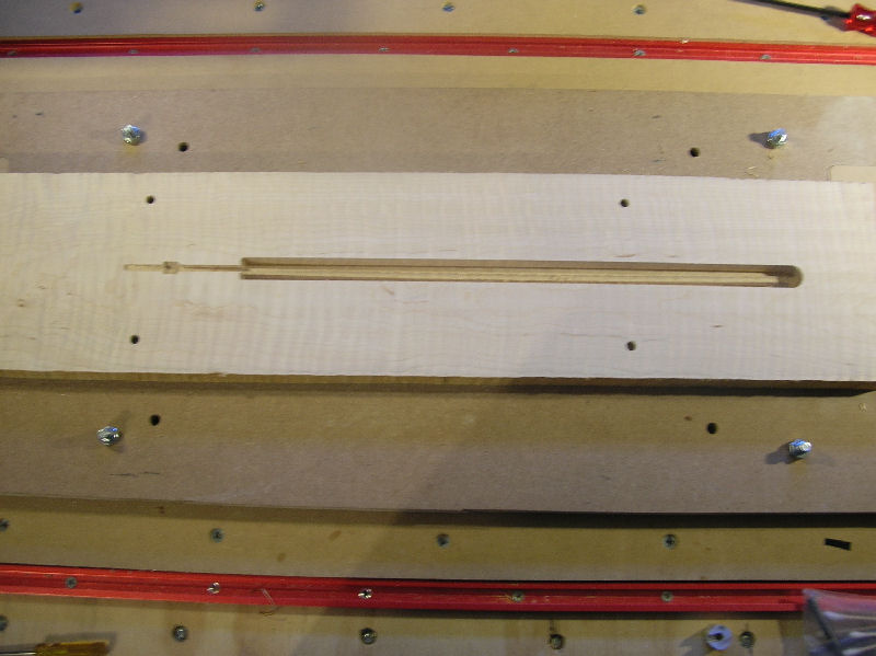
The area near the end of the trussrod route is for the bullet trussrod adjuster. The bullet is longer then this of course, but the CNC will not leave a nice round hole routing it like this, so the end of the bullet hole will be drilled with a jig. 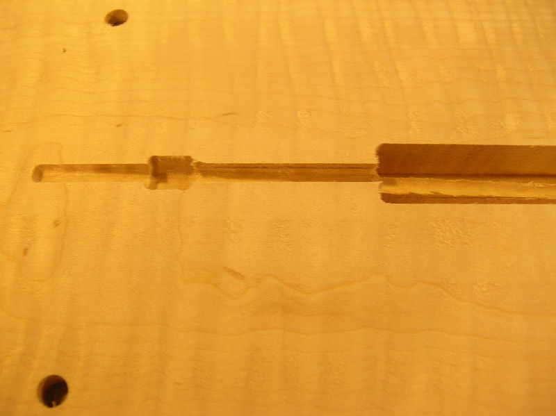
Here it is with the anchor installed. 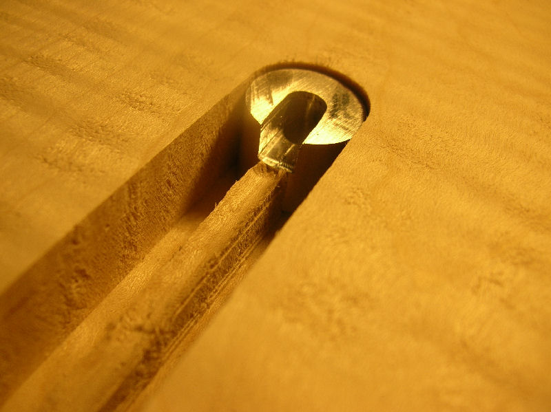
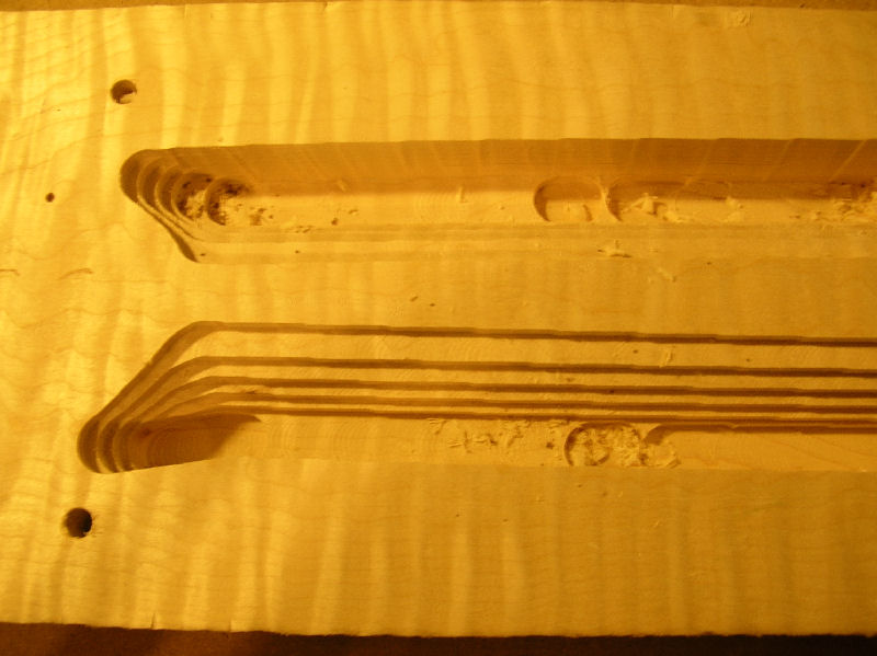
Next is the trussrod anchor route. 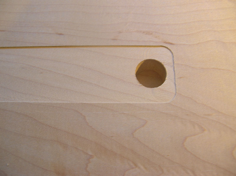
Then the trussrod channel. Again the channel is roughed with a 0.125" end mill and then the bottom of it is rounded to a 0.93" radius with a 0.125" ball mill. 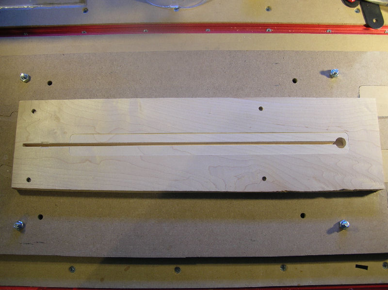
A large area is then milled with a 0.500" end mill. 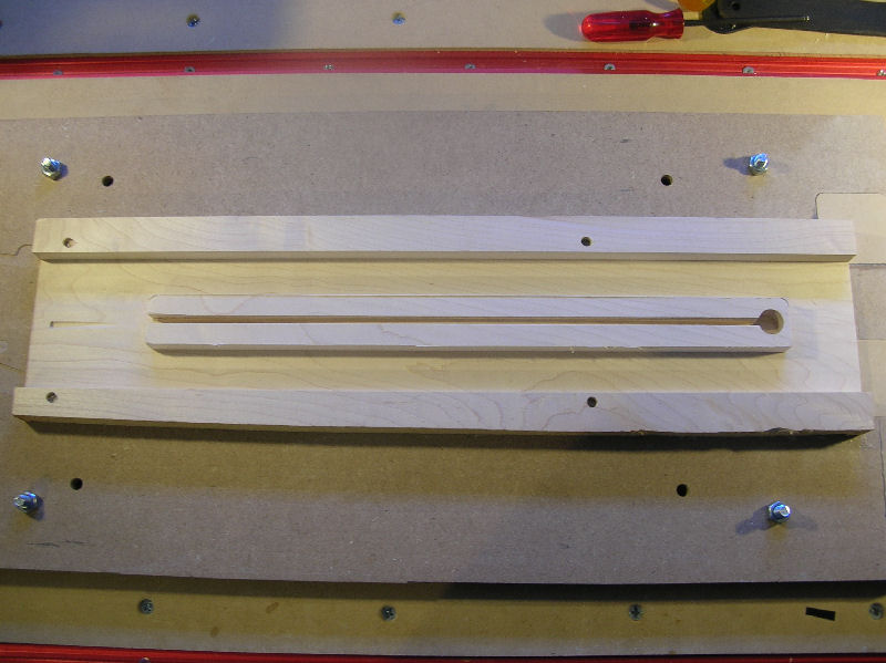
A 0.250 end mill performs the fine cutting around the trussrod cannel. 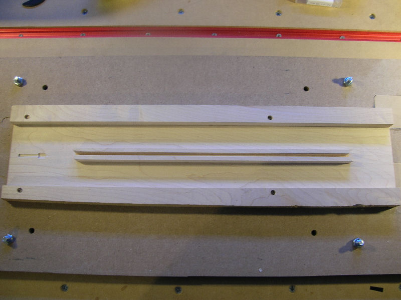
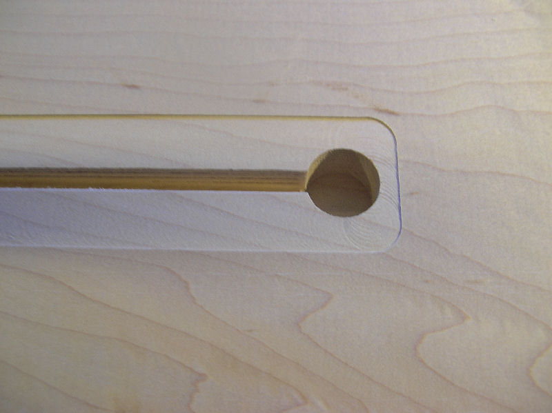
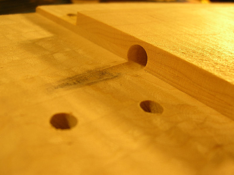
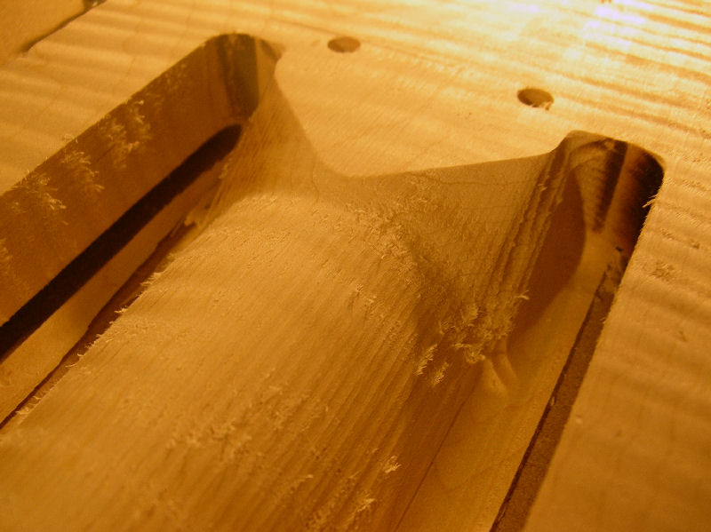
Here are the ends of the trussrod channel. 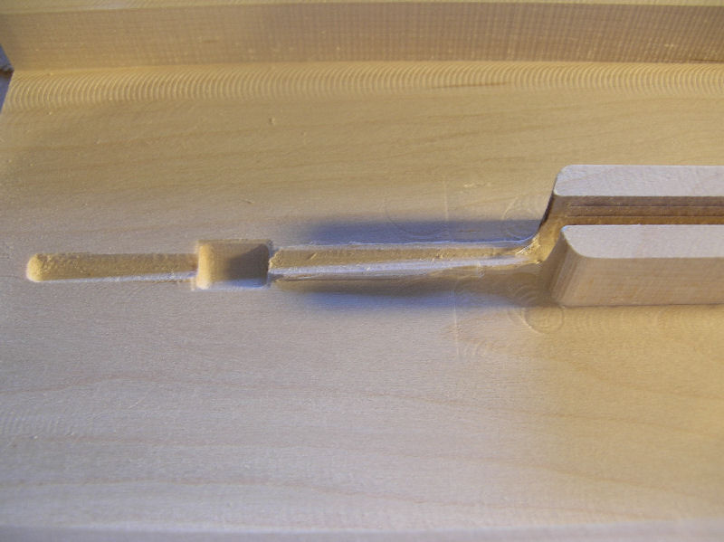
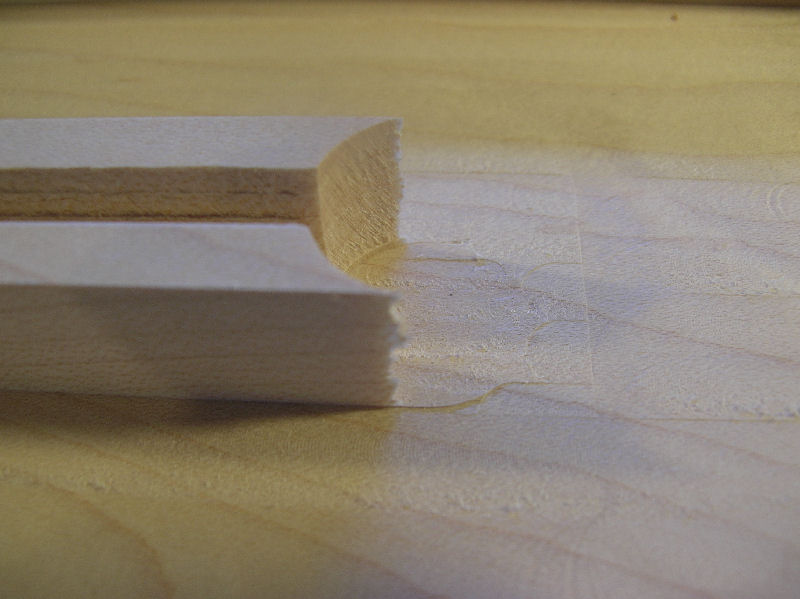
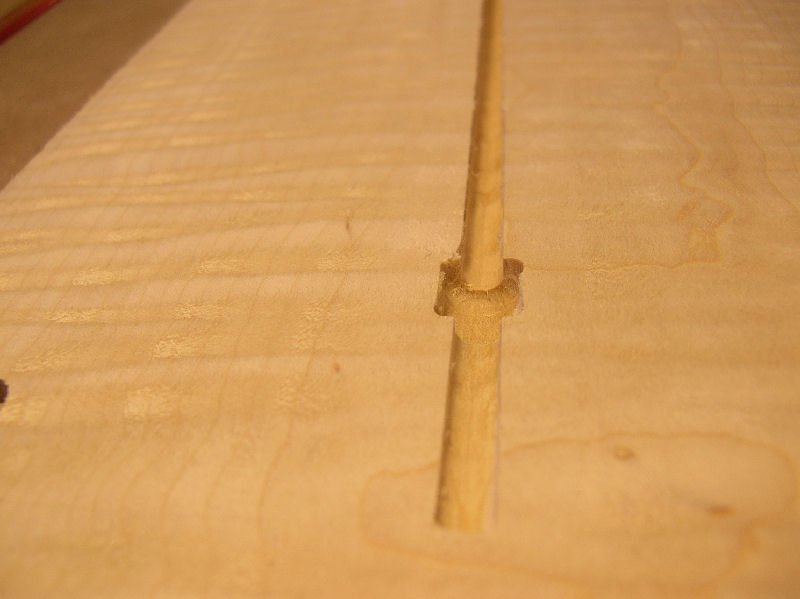
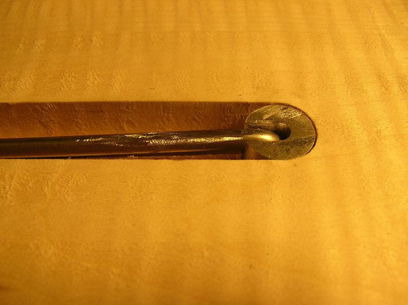
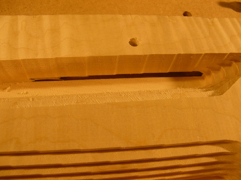
And with the trussrod and trussrod anchor installed. 
Here is the cap with the trussrod installed sitting on top of the base. 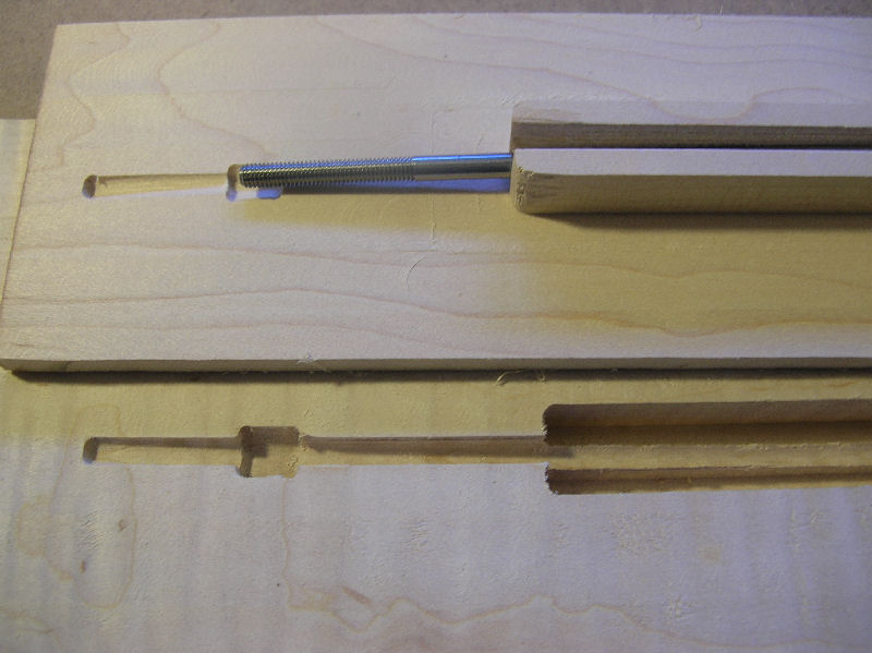
Here is the base with a scrapped section of a cap installed to show how tight the trussrod routes encase the trussrod with no air gaps. 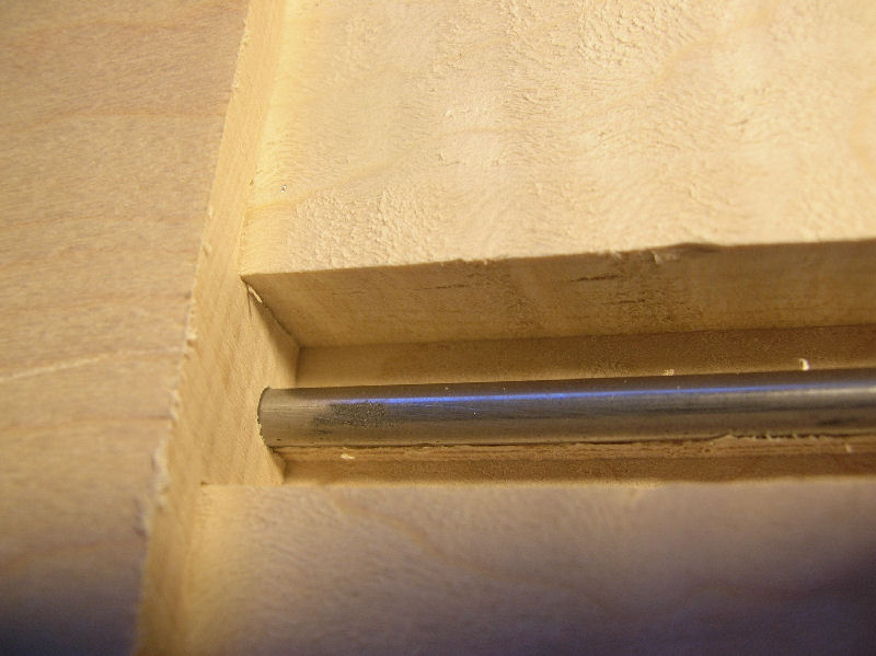
The base and cap are then glued together. 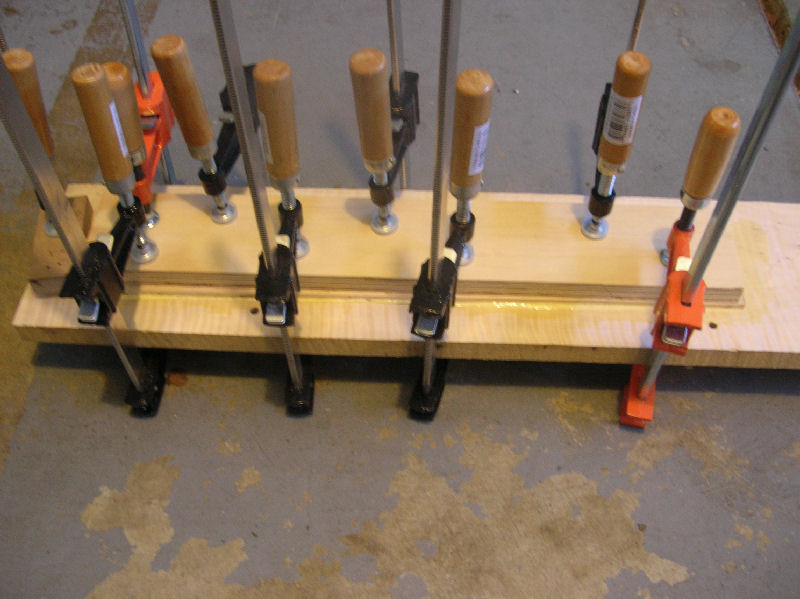
After the glued has cured, the base and cap are then mounted on the CNC. 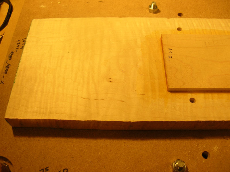
Here is the trussrod anchor jig. 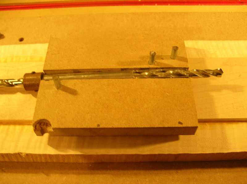
The trussrod bullet end hole is then drilled. 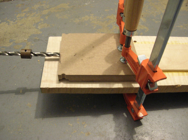
Here is the end of the trussrod bullet hole after drilling. 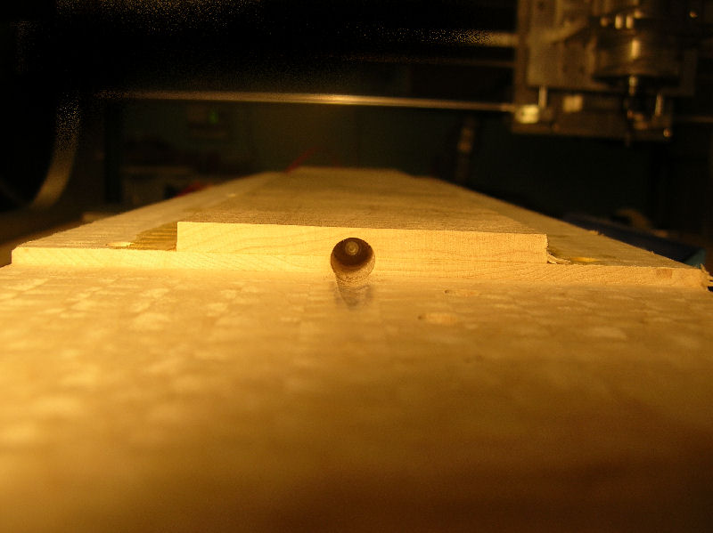
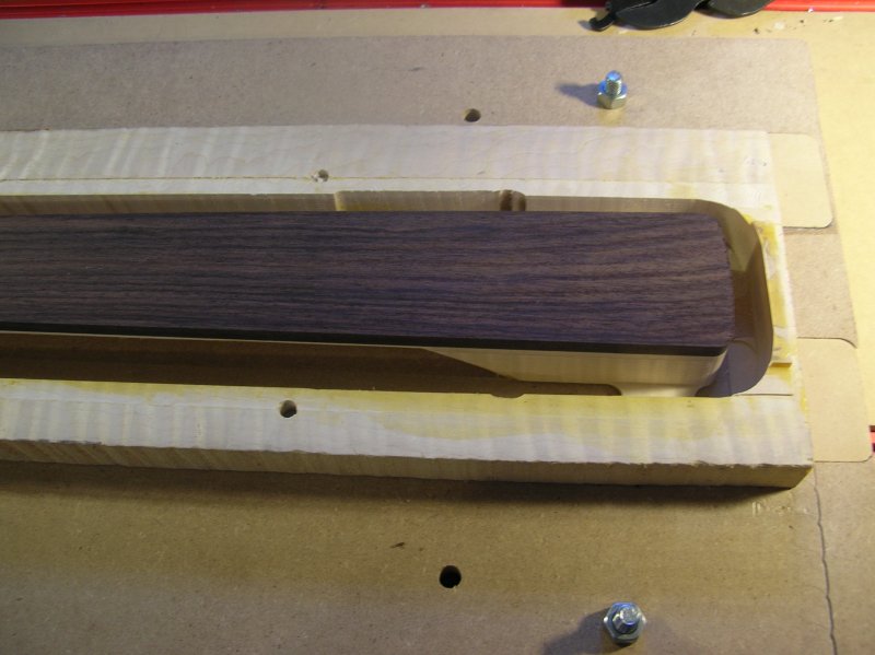
The backside of the neck is then contoured. 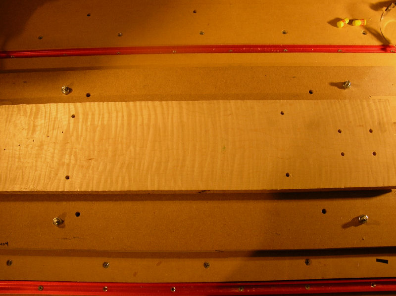
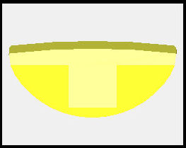
Below is the CAD file showing the back contour. 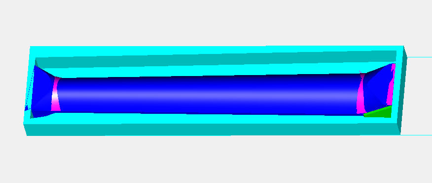
It is first roughed with a 0.500 end mill. 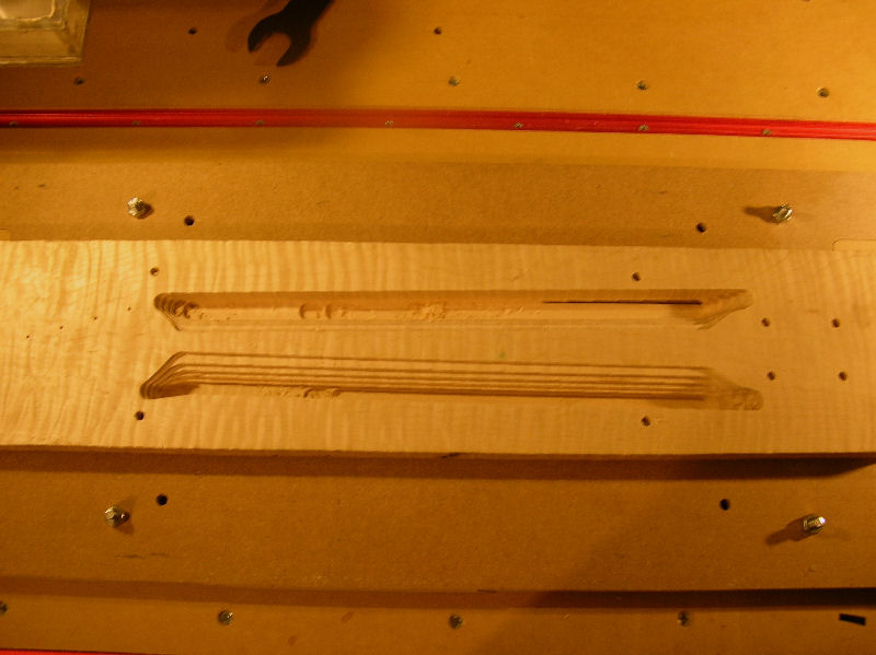
Then the fine cut is done with a 0.500 ball mill using a 0.05" stepover. 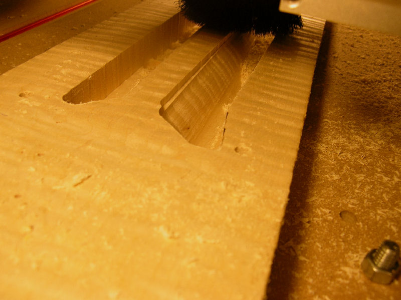
The neck is then flipped over and a 9.5" radius is cut into the neck cap 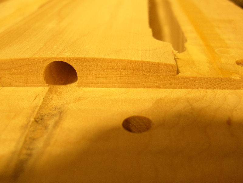
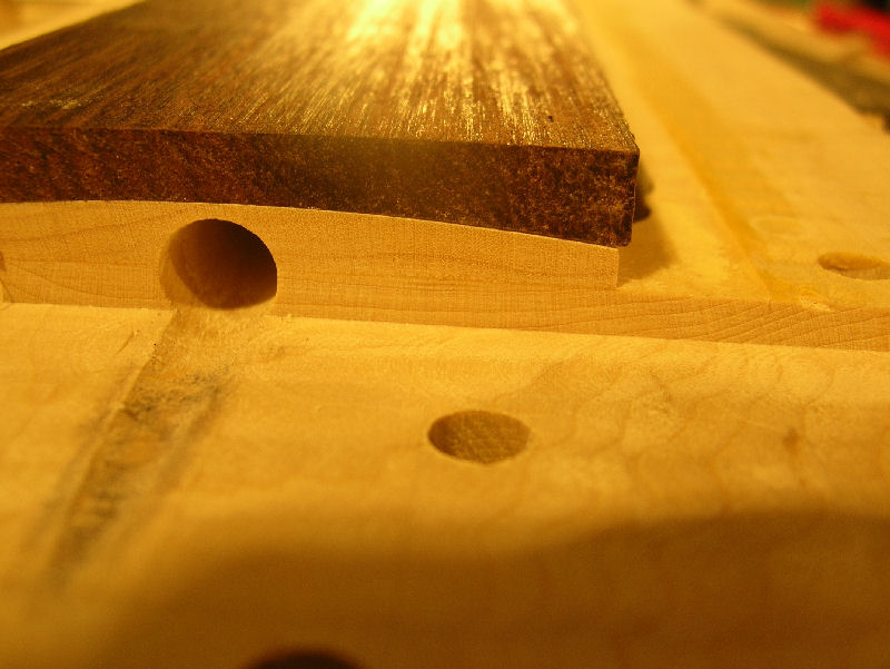
A negative 9.5" radius is cut into an Indian rosewood fretboard. 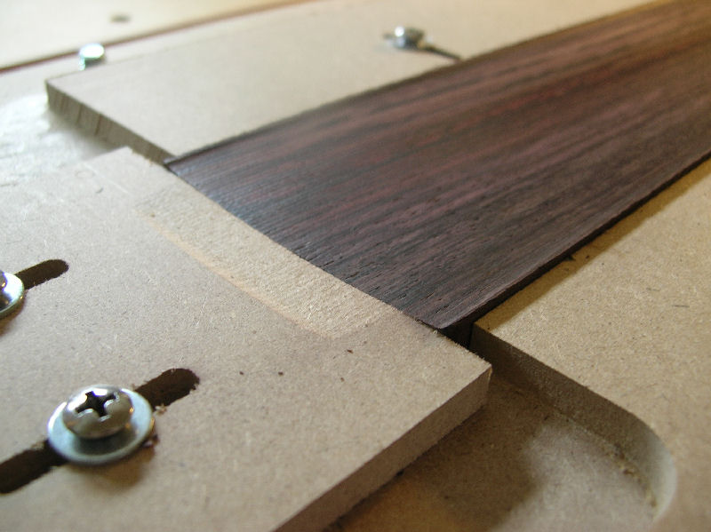
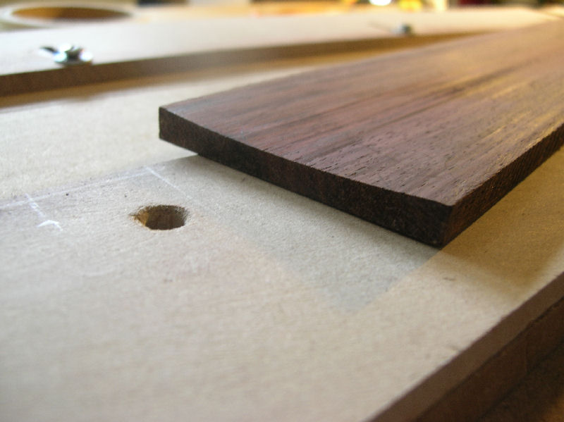
The fretboard is then glued to the top of the neck cap. 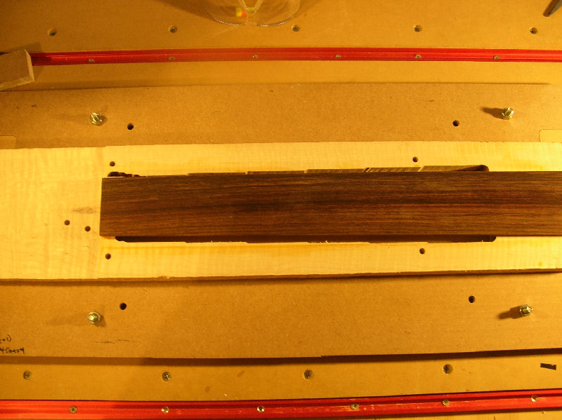
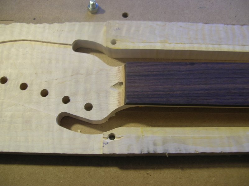
The headstock transition is cut with a 0.500 ball mill. 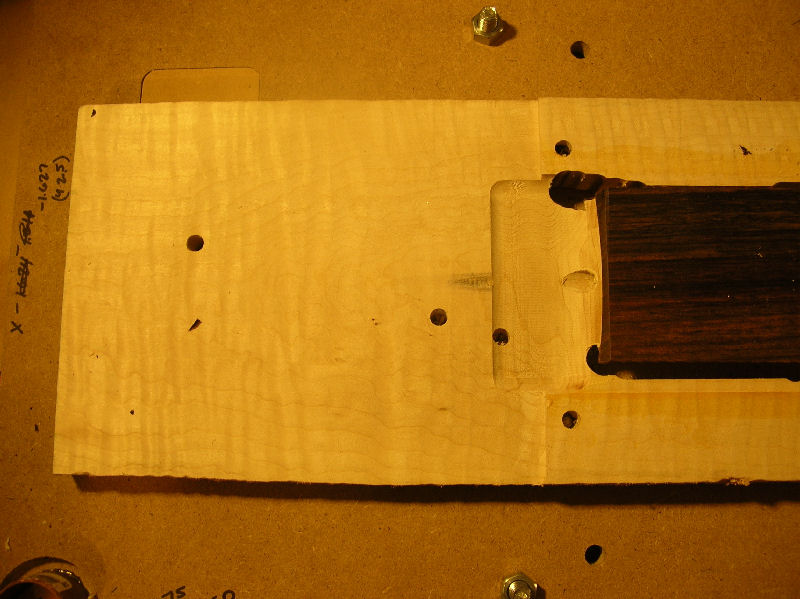
The headstock is milled to its final 0.590" thickness. Then the tuner holes are cut. 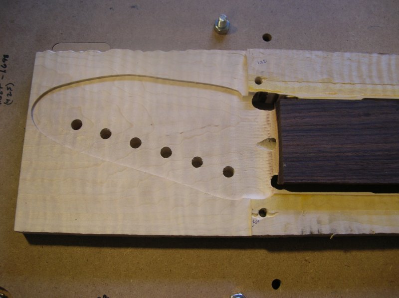
The main cutout from the headstock to the heel is done with a 0.500" end mill. Below is a CAD image showing the main cutout. 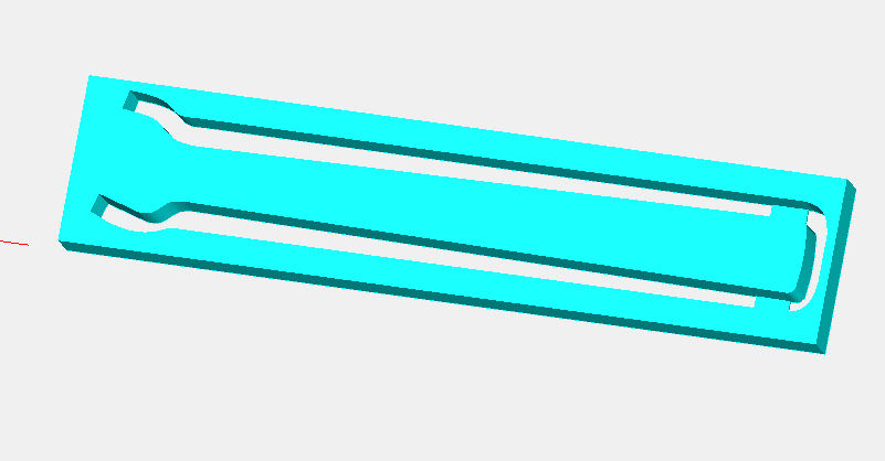
Here are photos after the cutout. 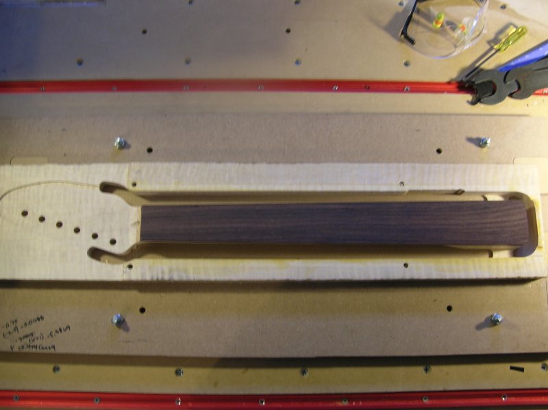
The headstock is cutout with a 0.250 end mill. Below is a CAD file of the headstock cutout. 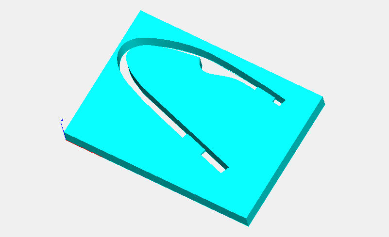
Here is the actual neck after the headstock cutout. 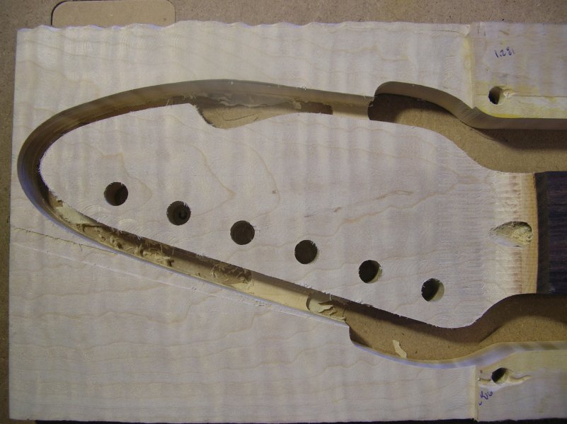
After sitting for a week to let the wood stress relive itself from all the cutting, the fretboard radius can now be cut. Here it is before. 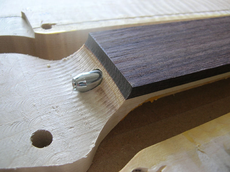
The fretboard radius is cut with a 0.500 ball mill with a 0.025" step over. Here it is after the radius is cut. 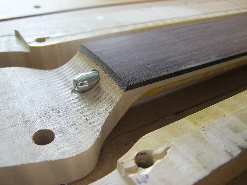
The radiused nut slot can now be cut with a 0.093 end mill. 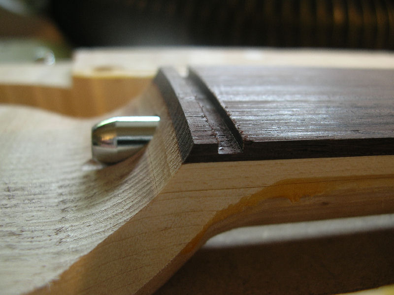
Then the holes for the position markers are cut with a 0.125" end mill. 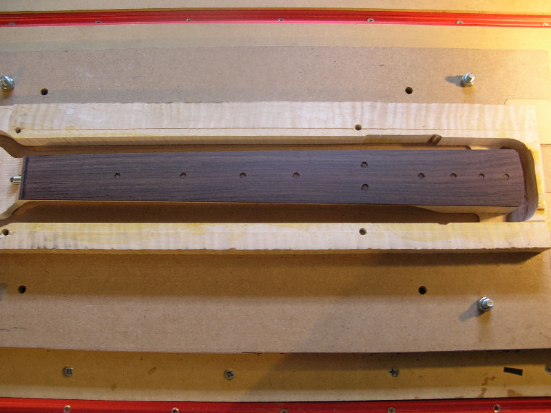
The moher of pearl position markers are then glued in position. 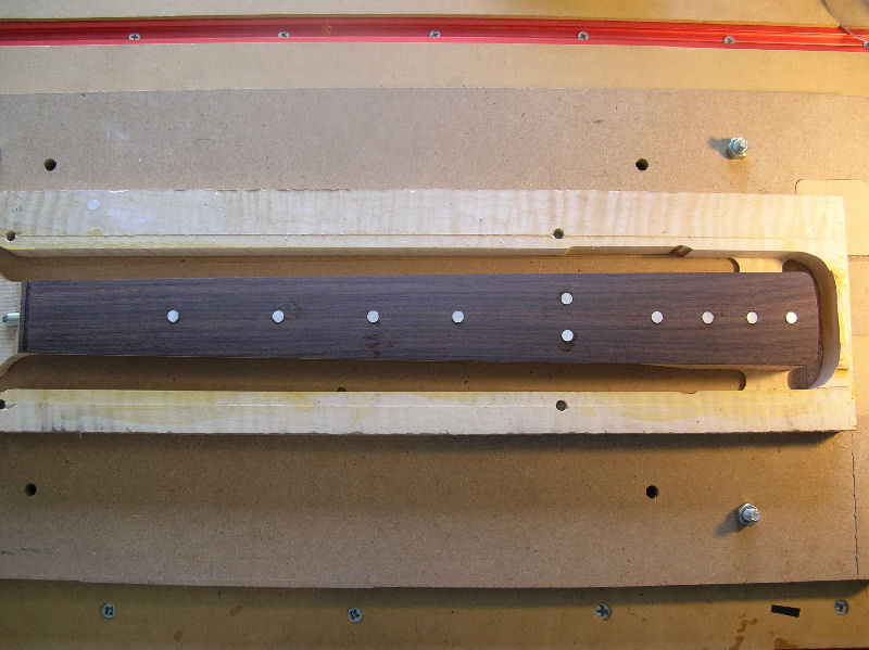
They are then sanded flush with the fretboard with a radiused sanding block. 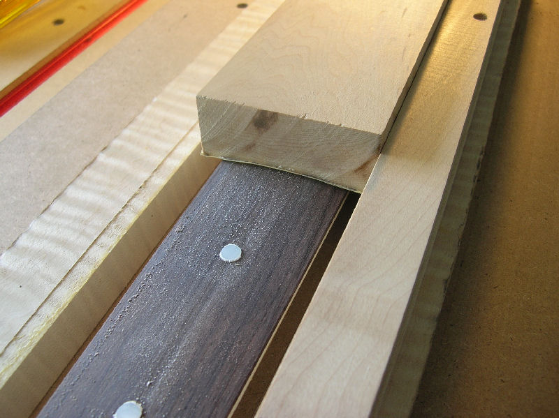
Here they are after sanding. 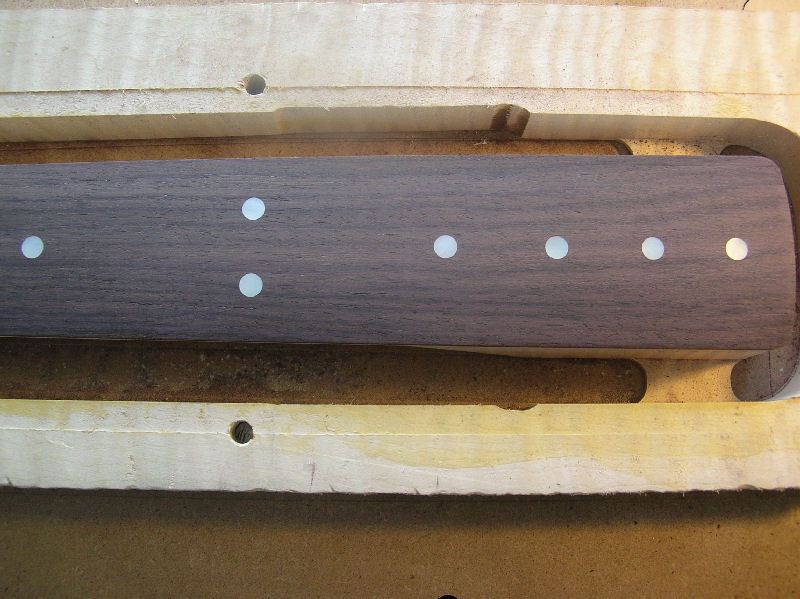
Then the fret slots are cut with a tiny 0.022" end mill. 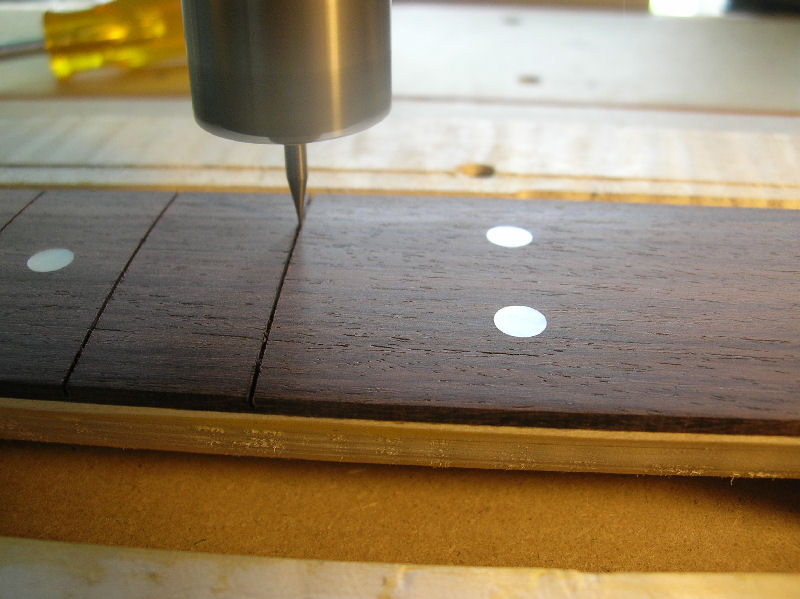
The tabs are cut away and the neck is then mounted sideways in a vise and the holes for the side marker dots are cut the old way, on a drill press. 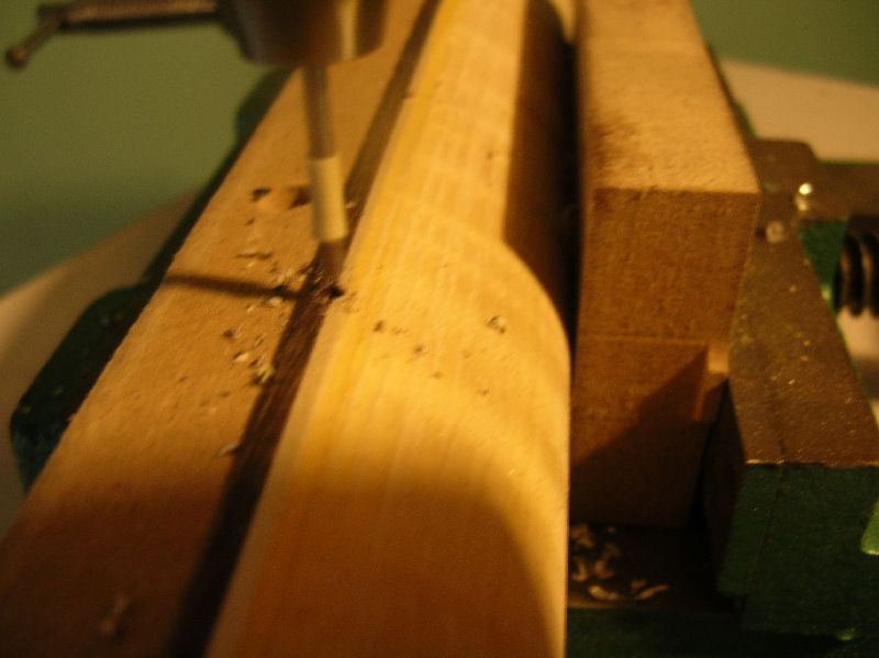
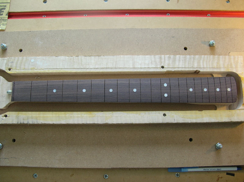
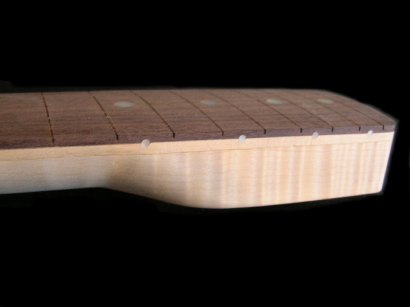
After some rough sanding, here are some images of the finished neck. 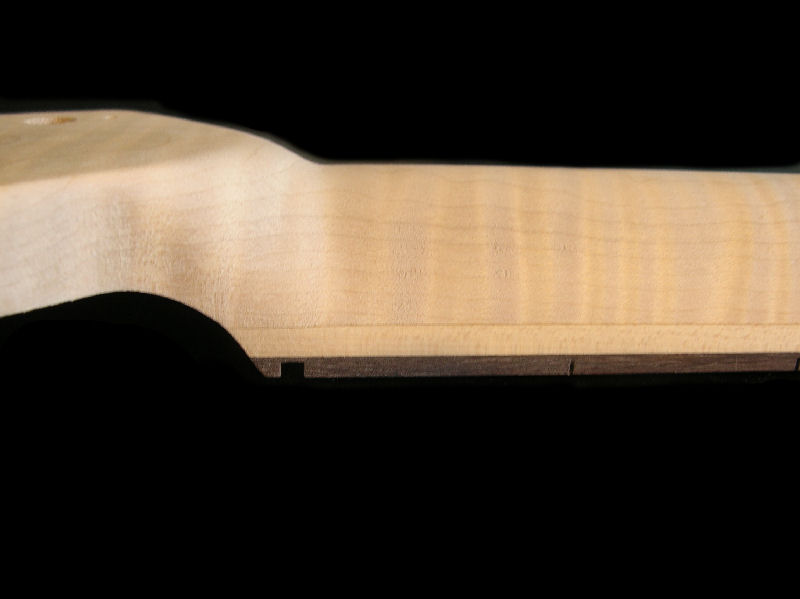
|